


Advantages:
1.Our Company Has Great Reputation In Domestic Market.
2.Good Quality Guaranteed With Reasonable Price.
3.OEM,ODM Are Welcomed.
4.Goods Will Be Delivered On Time.
5.Factory Selling Directly
Descriptions:
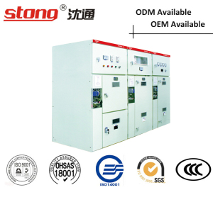
Tank-type(fixed) AC H.V. Metal-enclosed Switchgear
Product overview
XGN66-12 fixed metal-enclosed switchgear is a new brand of product,meet the requirement of GB3906 and DLT404,also meetinternational standards IEC298. The product is small in size, only half of the average size of the switch cabinet, and the circuit breaker has the advantages of good reliability and good performance.
Switch cabinet is 3.6kV, 7.2kV, 12kV phase alternating current, 50Hz single busbar indoor complete device as a receiving and distribution of electric energy use. And with the circuit control, protection and monitoring and other functions, can be used in various types of power plants, substations and miners, high-rise buildings and other places.
Type meaning
X-------Box type switchgear
G------Fixed type
N------Indoor type
66-----Design number
12-----Rated voltage
Z-------vacuum switch
Normal conditions of use
1, Altitude no more than 1000m;
2,ambient temperature:-25C~+40C, Day average no more than +35;
3,The level of inclination is not greater than 3 degrees;
4,Earthquake intensity is not more than 8 degrees;
5,No severe vibration and shock;
Structure features
1,The cabinet is made of high quality welded ;
2,The breaker room is located in the middle or lower part of the cabinet, convenient maintenance , installation and test;
3,The rotary switch is advanced and reliable, can go into the circuit breaker room for maintenance when the bus is charged.
4,Protection level IP2X
5,Equipped with forced mechanical locking device with complete function.
6,With reliable grounding system
7,The door is provided with an observation window, and the work of the components in the cabinet can be clearly observed.
8,Cable is lower than the front of the bottom of the cabinet, convenient for connection
XGN66-12(Z)
Tank-type(fixed) AC H.V. Metal-enclosed Switchgear
Main Technical Parameter
Layout schematic diagram

Switch cabinet layout schematic diagram
1. Door 7. Brow 13. Isolating switch 19. sensor
2. Lighting lamp 8. Wall bushing of busbar 14. pull rod 20. Bolt
3. Viewing window 9. Bolt 15. Rear sealing plate 21.washer
4. Operating mechanism 10. washer 16. Current transformer 22. washer
5. Small door plate 11. Washer 17. Vacuum circuit breaker 23. skeleton
6. Meter door 12. Nut 18. Isolating switch 24. Lightning arrester
Installation
Installation foundation reference
Post column
beam channel
Angle steel
the front of cabinet
The cable trench is determined according to the
bending radius of the cable.
The bottom plate layout
the first cable line
secondary cable line hole
corner mounting hole
the front of cabinet
Put into operation
The test and maintenance of cabinet before put into
operation.
A,According to the order required to check if the
installation of electrical components within the cabinet
model is consistent with the specifications.Check if the
fasteners are loose;make sure the first and secondary
wirings are correct ;operate the isolation switch,
grounding switch,circuit breaker,mechanical
interlocking 3~5 times,make sure there is no stuck,and
then add the lubricating oil to the mechanical parts.
B,According to the factory test report,check the level
,loop resistance and the mechanical characteristic of
circuit breaker of the switch cabinet.The test result
should be close to the factory test report.
Maintenance
1. The users should maintain the switch cabinet regularly.
including:
a: clean the dust inside,especially the surface of the
Insulating part.
b:check the mechanical operating parts, add the
lubricating oil regularly,keep it flexible.
c: the maintenance of circuit breaker,isolation
switch ,grounding switch and other components
according to their respective instructions.
d: check the contact of electric,
e: Check whether there is no over heat phenomenon,
and the grounding circuit is on the way.
f: Check if the fasteners are tightened
Random files and enclosures :
1,product certification,packing list
2,Installation instructions and sencondary wiring
diagram of switch cabinet and other
main components.
3,Energy storage and operating handle
4,other spare parts please consult with our company
Order notice
1,primary wiring diagram and primary wiring
arrangement diagram
2, schematic diagram , wiring diagram and terminal
diagram of secondary circuit.
3,primary,secondary device lists
4,Switch cabinet layout and the installation position of
bus bridge
5,spare parts and other special using conditions should
consult with our company.


 Packing&Shipping:

1.Our Company Has Great Reputation In Domestic Market.
2.Good Quality Guaranteed With Reasonable Price.
3.OEM,ODM Are Welcomed.
4.Goods Will Be Delivered On Time.
5.Factory Selling Directly
Descriptions:
Tank-type(fixed) AC H.V. Metal-enclosed Switchgear
Product overview
XGN66-12 fixed metal-enclosed switchgear is a new brand of product,meet the requirement of GB3906 and DLT404,also meetinternational standards IEC298. The product is small in size, only half of the average size of the switch cabinet, and the circuit breaker has the advantages of good reliability and good performance.
Switch cabinet is 3.6kV, 7.2kV, 12kV phase alternating current, 50Hz single busbar indoor complete device as a receiving and distribution of electric energy use. And with the circuit control, protection and monitoring and other functions, can be used in various types of power plants, substations and miners, high-rise buildings and other places.
Type meaning
X-------Box type switchgear
G------Fixed type
N------Indoor type
66-----Design number
12-----Rated voltage
Z-------vacuum switch
Normal conditions of use
1, Altitude no more than 1000m;
2,ambient temperature:-25C~+40C, Day average no more than +35;
3,The level of inclination is not greater than 3 degrees;
4,Earthquake intensity is not more than 8 degrees;
5,No severe vibration and shock;
Structure features
1,The cabinet is made of high quality welded ;
2,The breaker room is located in the middle or lower part of the cabinet, convenient maintenance , installation and test;
3,The rotary switch is advanced and reliable, can go into the circuit breaker room for maintenance when the bus is charged.
4,Protection level IP2X
5,Equipped with forced mechanical locking device with complete function.
6,With reliable grounding system
7,The door is provided with an observation window, and the work of the components in the cabinet can be clearly observed.
8,Cable is lower than the front of the bottom of the cabinet, convenient for connection
XGN66-12(Z)
Tank-type(fixed) AC H.V. Metal-enclosed Switchgear
Main Technical Parameter
- Main technical parameters and components of switch cabinet
| No. | Item | Unit | Technical parameters |
| 1 | Rated voltage | KV | 3.6,7.2,12 |
| 2 | Rated power frequency withstand voltage | KV | Ground,same:42; fracture:45 |
| 3 | Rated lightning impulse voltage | KV | Ground,same:75; fracture:85 |
| 4 | Rated frequency | HZ | 50 |
| 5 | Rated current | A | 630,1250 |
| 6 | Rated short-circuit breaking current(peak) | KA | 20,25,31.5 |
| 7 | Rated short-circuit current(peak) | KA | 50,63,80 |
| 8 | Rated dynamic current(peak) | KA | 50,63,80 |
| 9 | Lightning heat stable current(effective value) | KA | 20,25,31.5 |
| 10 | Protection level | IP2X | |
| 11 | Outline dimensions (width, depth, height) | mm | 900x1000x2300 |
| 12 | Weight | kg | ≈600 |
- Main technical parameters of ZN63-12 vacuum circuit breaker
| No. | Item | Unit | Technical parameters |
| 1 | Rated voltage | kV | 12 |
| 2 | Rated current | A | 630,1250 |
| 3 | Rated short-circuit breaking current | kA | 20,25,31.5 |
| 4 | Rated short-circuit current | kA | 50,63,80 |
| 5 | Rated short-time withstand current (4s effective value) | kA | 20,25,31.5 |
| 6 | Rated peak withstand current(peak) | kA | 50,63,80 |
| 7 | Mechanical life | time | 10000 |
| 8 | Rated short-time breaking current break time | time | 50 |
| 9 | Rated operating sequence | Off -0.3s-on-off -180s-on-off | |
| 10 | Distance between open contacts | mm | 11±1 |
| 11 | Contact travel | mm | 4±0.5 |
| 12 | Relative center distance | mm | 210 |
| 13 | Split speed | m/s | 1.2±0.2 |
| 14 | Closing speed | m/s | 0.6±0.2 |
| 15 | Split time | ms | ≤60 |
| 16 | Closing time | ms | ≤75 |
| 17 | Three-phase switching cycle | ms | ≤2 |
| 18 | Closing bouncing | ms | ≤2 |
| 19 | Loop resistance | μΩ | ≤45 |
| 20 | Allowable cumulative abrasion thickness of the contacts | mm | 3 |
- Technical parameters of other electrical components refer to their own Instructions.
- The program that the rated current of the switch cabinet higher than 1600A shall be negotiated with our company.
Layout schematic diagram
Switch cabinet layout schematic diagram
1. Door 7. Brow 13. Isolating switch 19. sensor
2. Lighting lamp 8. Wall bushing of busbar 14. pull rod 20. Bolt
3. Viewing window 9. Bolt 15. Rear sealing plate 21.washer
4. Operating mechanism 10. washer 16. Current transformer 22. washer
5. Small door plate 11. Washer 17. Vacuum circuit breaker 23. skeleton
6. Meter door 12. Nut 18. Isolating switch 24. Lightning arrester
Installation
- Install foundation please refer to the following pictures, the base channel highlights on 1-3mm, in 1 meter range the unevenness should not be more than 1.5mm, in the full length range no more than 5mm.
- Place the switch hinge on the base in order, adjust the install position, then fix it with M12 bolt or spot welding method, tight it between cabinet and cabinet with M8 bolt.
- Open the rear cover plate and install the main busbar and primary power supply, pay attention to clean the terminal contact surface and paint neutral Vaseline on it, after installing seal the cable hole.
- Connect the grounding busbar between cabinet and cabinet, make it into one along the direction of switch cabinet, check whether the work-grounding and protect-grounding are missing, and whether the grounding circuit is connected, work-grounding resistance should not be more than 1000μΩ, protect-grounding resistance should not be more than 4Ω.
- Install the secondary cable, introduce the cable from the bottom of the cabinet in the front, and let them enter along the side wall to the low voltage room, tap them on the terminal blocks; or enter them from the secondary small busbar on the cabinet top into the low voltage room, after installing seal the cable hole.
- Clean up dust and impurities in the cabinet.
Installation foundation reference
Post column
beam channel
Angle steel
the front of cabinet
The cable trench is determined according to the
bending radius of the cable.
The bottom plate layout
the first cable line
secondary cable line hole
corner mounting hole
the front of cabinet
Put into operation
The test and maintenance of cabinet before put into
operation.
A,According to the order required to check if the
installation of electrical components within the cabinet
model is consistent with the specifications.Check if the
fasteners are loose;make sure the first and secondary
wirings are correct ;operate the isolation switch,
grounding switch,circuit breaker,mechanical
interlocking 3~5 times,make sure there is no stuck,and
then add the lubricating oil to the mechanical parts.
B,According to the factory test report,check the level
,loop resistance and the mechanical characteristic of
circuit breaker of the switch cabinet.The test result
should be close to the factory test report.
Maintenance
1. The users should maintain the switch cabinet regularly.
including:
a: clean the dust inside,especially the surface of the
Insulating part.
b:check the mechanical operating parts, add the
lubricating oil regularly,keep it flexible.
c: the maintenance of circuit breaker,isolation
switch ,grounding switch and other components
according to their respective instructions.
d: check the contact of electric,
e: Check whether there is no over heat phenomenon,
and the grounding circuit is on the way.
f: Check if the fasteners are tightened
Random files and enclosures :
1,product certification,packing list
2,Installation instructions and sencondary wiring
diagram of switch cabinet and other
main components.
3,Energy storage and operating handle
4,other spare parts please consult with our company
Order notice
1,primary wiring diagram and primary wiring
arrangement diagram
2, schematic diagram , wiring diagram and terminal
diagram of secondary circuit.
3,primary,secondary device lists
4,Switch cabinet layout and the installation position of
bus bridge
5,spare parts and other special using conditions should
consult with our company.
Packing&Shipping: